
GWVT Series
GWVT Series Special and Process Gas Screw Compressors
The GWVT Series Special and Process Gas Screw Compressors are designed for process gas compression applications that differ from conventional compressed air systems. Equipment configurations can be tailored to the properties of the specific gas, working pressure, flow rate, and project operating conditions.
The series offers working pressure ratings of 0.8 MPa, 1.0 MPa, and 1.25 MPa, covering a range of motor power ratings and FAD capacities. The technical documentation also provides specifications for cooling water inlet and outlet connection sizes, cooling water requirements, overall dimensions, weight, and gas outlet connections.
Special and process gases may vary significantly in composition, temperature, pressure, corrosiveness, flammability, and process requirements. Therefore, the final GWVT model should not be selected solely on the basis of general product specifications. Complete gas composition and operating condition data should be provided for each project so that technical personnel can confirm the appropriate equipment configuration.

Features
Product Features
- Designed for special and process gas compression applications.
- Available in models covering a range of motor power ratings and flow capacities.
- Offers working pressure ratings of 0.8, 1.0, and 1.25 MPa, among others.
- Can be configured to suit specific gas properties and project operating conditions.
- The specification table provides engineering data on cooling water requirements, equipment dimensions, weight, and gas outlet connections.
- Equipment selection must also consider the properties of the gas being compressed, rather than relying solely on conventional air compressor specifications.
Technical structure
Technical Structure & Mechanical Description
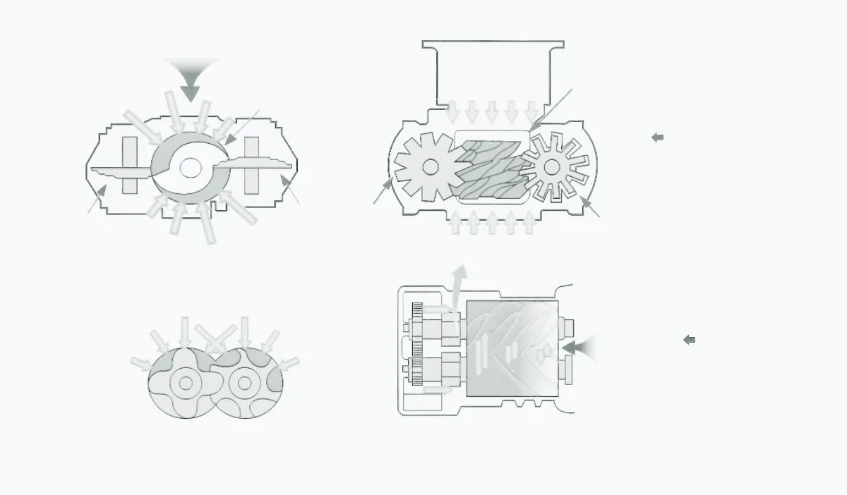
The structural diagram is provided to help explain key components and load relationships within the unit. Specific structures vary by model, power, pressure, cooling method, and project configuration; refer to the corresponding technical documentation for actual details.
System flow
System Process
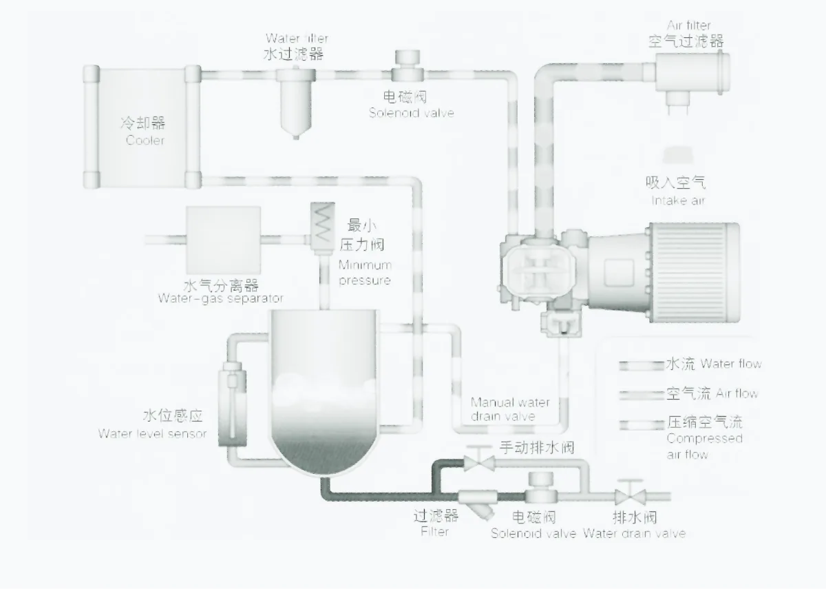
The system flow diagram illustrates the main stages of compression, cooling, separation, and air delivery. The actual process varies by model, cooling method, air-treatment configuration, and project requirements.
Product parameters
Specifications
| 型号Model | 最大工作压力Max’ pMPa | 容积流量FADm³/min | 电机功率PowerkW | 噪音NoisedB | 冷却水进出口径C, W(In, Out) | 冷却水量 ≤进气温度C, W’s Qt/h | 润滑水量Lubricating WaterL | 外形尺寸DimensionL×W×H mm | 重量Weightkg | 出气管径Air outlet |
|---|---|---|---|---|---|---|---|---|---|---|
| GW18VA/WR | 0.81.01.25 | 0.9-3.100.9-2.620.6-2.10 | 18 | 65 | DN32 | 4 | 1400×900×1450 (A) 1350×950×1250 (W) |
705 (A) 670 (W) |
1″ / DN25 3/4″ / DN20 |
|
| GW22VA/WR | 0.81.01.25 | 1.1-3.420.97-3.150.85-2.62 | 22 | 65 | DN32 | 5 | 1400×900×1450 (A) 1350×850×1250 (W) |
745 (A) 710 (W) |
1″ / DN25 | |
| GW30VA/WR | 0.81.01.25 | 1.55-5.051.25-4.201.10-3.18 | 30 | 67 | DN32 | 7.5 | 1850×1150×1500 (A) 1500×1150×1300 (W) |
1100 (A) 900 (W) |
1-1/4″ / DN32 | |
| GW37VA/WR | 0.81.01.25 | 1.91-6.101.60-5.801.42-5.00 | 37 | 67 | DN32 | 9 | 1850×1150×1500 (A) 1500×1150×1300 (W) |
1150 (A) 950 (W) |
1-1/4″ / DN32 | |
| GW45VWR | 0.81.01.25 | 2.50-7.801.91-6.151.70-5.65 | 45 | 70 | DN50 | 10 | 1800×1300×1670 | 1280 | 2″ / DN50 1-1/4″ / DN32 |
|
| GW55VWR | 0.81.01.25 | 3.0-9.602.50-8.552.30-7.45 | 55 | 70 | DN50 | 13 | 1800×1300×1670 | 1320 | 2″ / DN50 | |
| GW75VWR | 0.81.01.25 | 3.95-12.603.4-11.423.0-9.85 | 75 | 73 | DN50 | 18 | 1800×1300×1670 | 1420 | 2″ / DN50 | |
| GW90VWR | 0.81.01.25 | 5.0-16.04.30-14.053.72-13.10 | 90 | 73 | DN50 | 20 | 2200×1550×1800 | 1460 | DN65 DN50 |
|
| GW110VWR | 0.81.01.25 | 6.0-19.505.07-16.804.65-15.15 | 110 | 78 | DN50 | 22 | 2200×1550×1800 | 2300 | DN65 | |
| GW132VWR | 0.81.01.25 | 6.75-22.526.0-20.305.07-18.25 | 132 | 78 | DN50 | 26 | 2400×1750×1800 | 2340 | DN65 | |
| GW160VWR | 0.81.01.25 | 8.5-28.117.6-24.506.7-22.15 | 160 | 80 | DN50 | 33 | 3200×2000×2080 2400×1750×1800 |
2750 2500 |
DN80 DN65 |
|
| GW185VWR | 0.81.01.25 | 10-33.658.72-28.507.75-24.50 | 185 | 80 | DN50 | 38 | 3200×2000×2080 2400×1750×1800 |
2970 2600 |
DN80 DN65 |
|
| GW200VWR | 0.81.01.25 | 11.2-36.659.68-32.759.2-27.50 | 200 | 82 | DN50 | 44 | 3200×2000×2080 | 3300 | DN100 | |
| GW220VWR | 0.81.01.25 | 12.2-39.5011.2-35.809.0-29.50 | 220 | 82 | DN50 | 48 | 3200×2000×2080 | 3350 | DN100 | |
| GW250VWR | 0.81.01.25 | 13.5-41.0012.3-36.3010.2-34.50 | 250 | 82 | DN50DN65 | 5063 | 3200×2000×2080 | 3500 | DN100 |
Note: This table has been extracted from the original GWVT product documentation and follows the existing “one model per row” web table structure. For each model, the 0.8 / 1.0 / 1.25 MPa pressure ratings and their corresponding FAD ranges are arranged vertically within the same cells, maintaining the order shown in the original table. The “Lubricating Water Requirements” column contains no values in the original documentation, so the corresponding cells in the web table have been left blank without adding any assumed values. For the GW250VWR model, the cooling water inlet and outlet connection sizes and cooling water requirements are displayed on two lines in the original table. These entries have been preserved as presented, without making additional assumptions about their individual correspondence to the three pressure ratings.
Selection Guide
Among the six product series, the GWVT Series requires the most extensive preliminary information before equipment selection.
The first step is not to select the motor power rating, but to identify the gas to be compressed, including its name, main components, concentration range, and whether liquids, particles, or other accompanying substances may be present.
The following operating parameters should then be determined:
Inlet pressure → Required outlet pressure → Actual required flow rate → Inlet temperature → Continuous or intermittent operation.
The pressure ratings and FAD ranges in the specification table can then be used to shortlist suitable base models.
Different process gases may impose different requirements on materials, seals
Industry application
Industry Applications
The following links cover typical industry applications. Product suitability for a specific operating condition should be confirmed based on the medium, pressure, flow, air quality, cooling conditions, and project safety requirements.