
GWVL series
GWVL Series Smart Water-Lubricated Oil-Free Low-Pressure Screw Air Compressor
The GWVL Series smart water-lubricated oil-free low-pressure screw air compressors are designed for low-pressure compressed air applications. Featuring a water-lubricated oil-free screw compression system, the series is primarily available in working pressure ratings of 0.25 MPa, 0.3 MPa, and 0.4 MPa.
The series covers motor power ratings of approximately 30–185 kW, with different models providing corresponding volumetric flow rates. Models can be selected according to the operating pressure and air demand of the low-pressure air supply equipment.
The product documentation provides specifications for cooling water inlet and outlet connection sizes, cooling water requirements, lubricating water requirements, overall dimensions, weight, and air outlet connection size. These parameters can be used as a reference for equipment layout and piping configuration in low-pressure compressed air systems.

Features
Product Features
- Specifically designed for low-pressure compressed air applications.
- Available in three main working pressure ratings: 0.25, 0.3, and 0.4 MPa.
- Water-lubricated oil-free screw compression system.
- Offers models with different volumetric flow rates at lower operating pressures.
- Specifications cover cooling requirements, installation dimensions, equipment weight, and connection details.
Technical structure
Technical Structure & Mechanical Description
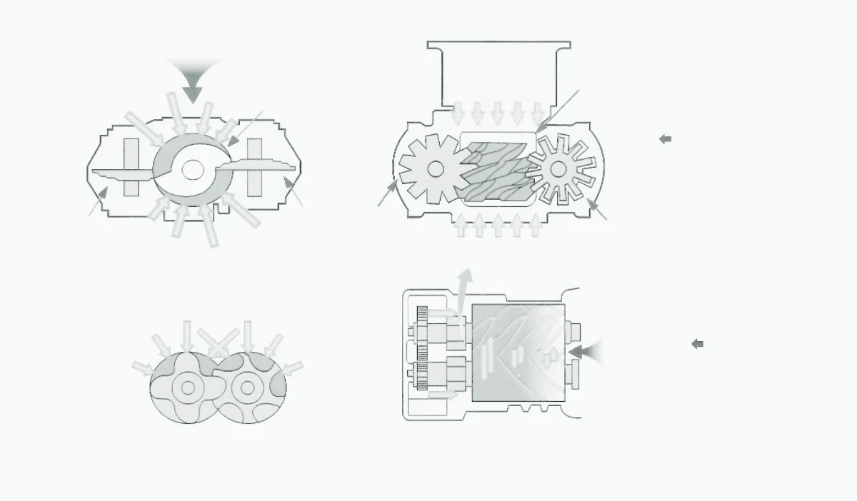
The structural diagram is provided to help explain key components and load relationships within the unit. Specific structures vary by model, power, pressure, cooling method, and project configuration; refer to the corresponding technical documentation for actual details.
System flow
System Process
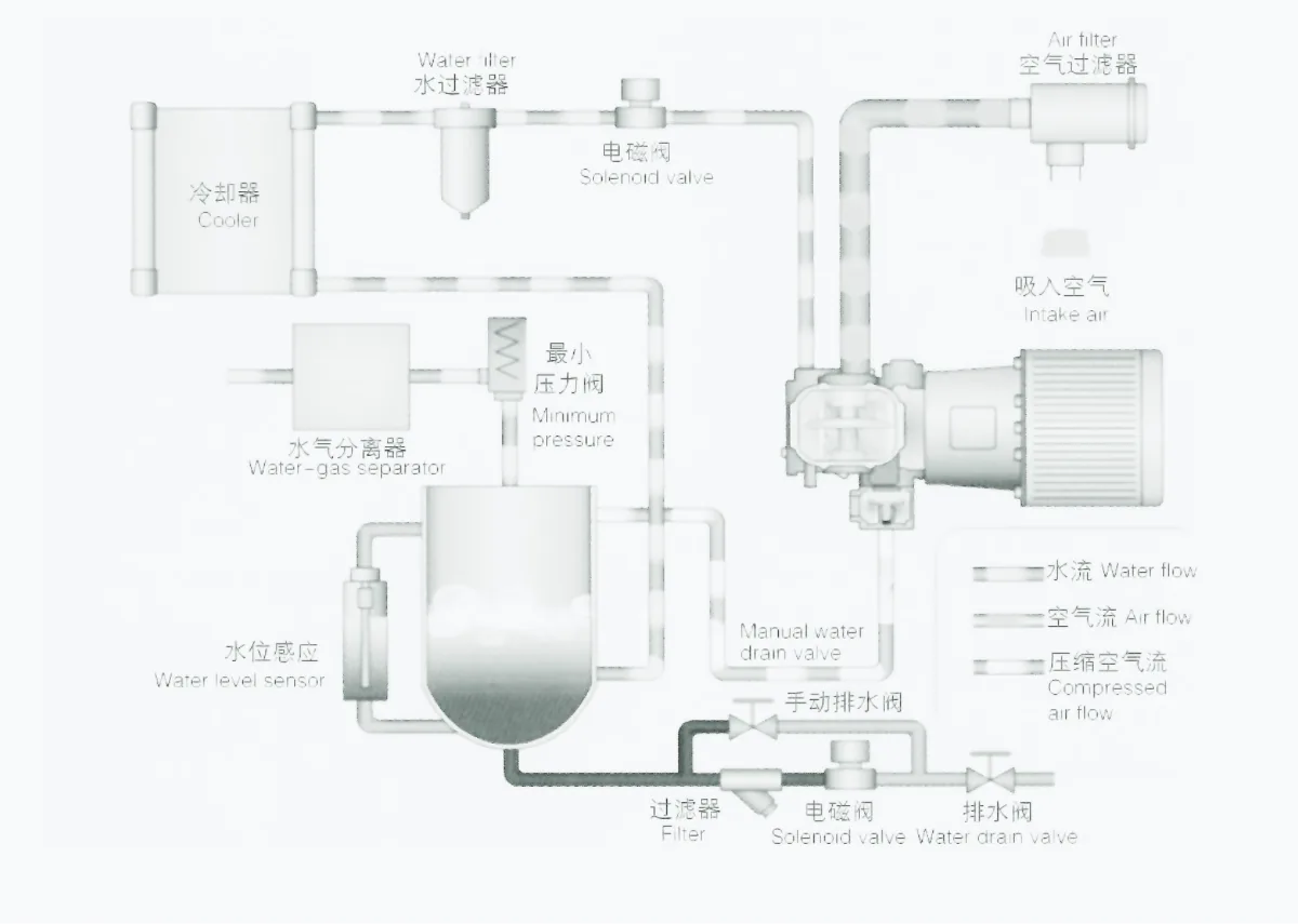
The system flow diagram illustrates the main stages of compression, cooling, separation, and air delivery. The actual process varies by model, cooling method, air-treatment configuration, and project requirements.
Product parameters
Specifications
| 型号Model | 最大工作压力Max’ pMPa | 容积流量FADm³/min | 电机功率PowerkW | 噪音NoisedB | 冷却水进出口径C, W(In, Out) | 冷却水量 ≤进气温度C, W’s Qt/h | 润滑水量Lubricating WaterL | 外形尺寸DimensionL×W×H mm | 重量Weightkg | 出气管径Air outlet |
|---|---|---|---|---|---|---|---|---|---|---|
| GW30VA/WL | 0.250.30.4 | 8.07.806.70 | 30 | 66 | DN32 | 7.5 | 90 | 1980×1300×1760 (A) 1800×1300×1670 (W) |
1400 (A) 1200 (W) |
2″ / DN50 |
| GW37VA/WL | 0.250.30.4 | 10.219.68.55 | 37 | 66 | DN32 | 9 | 90 | 1980×1300×1760 (A) 1800×1300×1670 (W) |
1450 (A) 1250 (W) |
2″ / DN50 |
| GW45VA/WL | 0.250.30.4 | 13.2011.2010.00 | 45 | 69 | DN50 | 10 | 120 | 2100×1600×1880 (A) 1800×1300×1670 (W) |
1690 (A) 1480 (W) |
DN65 |
| GW55VA/WL | 0.250.30.4 | 17.0016.5015.50 | 55 | 69 | DN50 | 13 | 120 | 2400×1300×1760 (A) 1800×1300×1670 (W) |
1770 (A) 1520 (W) |
DN80 DN65 |
| GW75VWL | 0.250.30.4 | 20.5019.5518.50 | 75 | 72 | DN50 | 18 | 180 | 2200×1500×1800 | 1620 | DN100 DN80 |
| GW90VWL | 0.250.30.4 | 24.0023.1021.50 | 90 | 72 | DN50 | 20 | 180 | 2200×1500×1800 | 1660 | DN100 |
| GW110VWL | 0.250.30.4 | 30.5029.8027.16 | 110 | 77 | DN50 | 22 | 300 | 2700×1800×2050 | 2500 | DN125 |
| GW132VWL | 0.250.30.4 | 33.2032.2030.50 | 132 | 77 | DN50 | 26 | 300 | 2700×1800×2050 | 2640 | DN125 |
| GW160VWL | 0.250.30.4 | 43.1540.5036.00 | 160 | 79 | DN50 | 33 | 360 | 2700×1800×2050 | 3050 | DN125 |
| GW185VWL | 0.250.30.4 | 46.0042.3040.00 | 185 | 79 | DN50 | 38 | 360 | 2700×1800×2050 | 3170 | DN125 |
Note: This table has been extracted from the original GWVL product documentation and follows the existing “one model per row” web table format. For each model, the 0.25 / 0.3 / 0.4 MPa pressure ratings and their corresponding FAD values are arranged vertically within the same cell, maintaining the original order. Multiple entries for dimensions, weight, and air outlet connection size have been preserved exactly as presented in the original documentation, without making any additional assumptions about their correspondence.
Selection Guide
The most important consideration when selecting a GWVL Series model is to avoid directly applying the selection criteria used for conventional 0.8 MPa air compressors.
If the actual air-consuming equipment requires only 0.25–0.4 MPa, the compressor discharge pressure should first be determined based on the required pressure at the point of use and the pressure losses in the piping system. An appropriate low-pressure model can then be selected.
Next, verify the FAD at 0.25, 0.3, or 0.4 MPa against the actual required flow rate.
For low-pressure systems with high flow requirements, attention should also be paid to the main pipeline diameter, piping length, and local flow resistance to avoid additional pressure losses caused by undersized piping.
Industry application
Industry Applications
The following links cover typical industry applications. Product suitability for a specific operating condition should be confirmed based on the medium, pressure, flow, air quality, cooling conditions, and project safety requirements.